- Joined
- Jul 9, 2023
- Messages
- 109
my build is based off of a 16-bit ISA backplane, with a Arduino Mega2560 clone for the MCU.


in the third image, you can see my UP3593 on the "test track".
also note, these images are from a while back, and my workbench has become quite a bit more cluttered as of late.
the plan with the ISA back-plane, is to connect the I2C and SPI bus pins to it, and allow easier expansion. so far, i have just the one card, so it looks rather "over engineered". while the main-board and back-plane are 16-bit, i have only found 8-bit ISA prototyping boards available, so i will have to limit it to just those bus rails. my original plan was to have a separate card for the Ethernet adapter, motor-shields, and GPIO expansion. then i built that hodge-podge mess above... though once the SPI and I2C are routed to the ISA bus, it would be simple to move the Ethernet to a card. i would just need to also add the support pins, like chip-select and interrupts. i think i should also route the reset pin to the ISA as well.
the EX_FastClock project could also be moved to it's own project, with the serial connection in place. as the EX_FastClock uses just one-way serial, i think, it could just be connected via a RS485 connection for distance.
the initial plan for GPIO was for on-board, or on-card, MCP23017 chips to expand the GPIO. this will be fine. and as for turnout control, i was going to use servos, controlled locally, but now i am thinking of making remote modules that take a digital signal, and change it to either slipper-motor (tortoise) control, or servo control. but it can be done easily with a smaller MCU. but the smaller MCU ca be positioned local to the action to e performed.
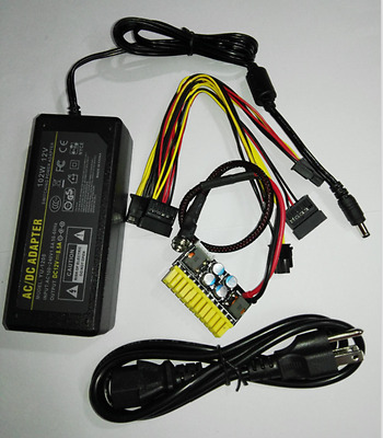
as far as power supplies, i think i currently use an ATX power-supply, but i am leaning more toward a single big power supply, set for 15V, with fuse blocks to distribute power, and DC-to-DC converters to drop the voltage from the main PSU down to needed levels. in theory this should work... i have no idea if the big PSU is double-shielded, or not. but i hope to figure out some circuit protection to shutdown the power if it surges at all. maybe a crowbar circuit of sorts. after-all, the big PSU is rated for some fair amps. ...or i could just wing it, as i usualy do, and throw caution to the wind...
the big PSU can supply 100A at up to 15Vdc. it is a RV power converter. it will be using a grounded outlet, so the frame will be grounded. i can't get high enough current to supply everything by using 400 different power blocks. i don't have that kind of funds.
now, the PSU will likely not have very clean power, but i can filter it a bit, and then filter it more in my circuits. even though last time i checked the PSU, it really wasn't that bad, noise-wise. but a little extra filtering can't hurt. that way i know my track signals are good and clean. even just tossing in some filter caps may be enough, compaired to what i used before, that worked just fine...
i could easily connect my oscilliscope to the PSU and see how noisy it is...
Now, the question remains on how to mount the whole contraption... i have a small AV rack i built that i could make use of. just have to make sure it has ventalation for PSU cooling. the front door is currently hollow so i could put a Lexan window in it, but i may just install a 1/4in or 3/8in panel to mount the LCD, some status LEDs, power switch, and so forth. the back panel will be removable for access. i think i even still have the original back panel. the back will contain the track wiring connectors, and maybe some other connections, as needed. don't know yet.
in the third image, you can see my UP3593 on the "test track".
also note, these images are from a while back, and my workbench has become quite a bit more cluttered as of late.
the plan with the ISA back-plane, is to connect the I2C and SPI bus pins to it, and allow easier expansion. so far, i have just the one card, so it looks rather "over engineered". while the main-board and back-plane are 16-bit, i have only found 8-bit ISA prototyping boards available, so i will have to limit it to just those bus rails. my original plan was to have a separate card for the Ethernet adapter, motor-shields, and GPIO expansion. then i built that hodge-podge mess above... though once the SPI and I2C are routed to the ISA bus, it would be simple to move the Ethernet to a card. i would just need to also add the support pins, like chip-select and interrupts. i think i should also route the reset pin to the ISA as well.
the EX_FastClock project could also be moved to it's own project, with the serial connection in place. as the EX_FastClock uses just one-way serial, i think, it could just be connected via a RS485 connection for distance.
the initial plan for GPIO was for on-board, or on-card, MCP23017 chips to expand the GPIO. this will be fine. and as for turnout control, i was going to use servos, controlled locally, but now i am thinking of making remote modules that take a digital signal, and change it to either slipper-motor (tortoise) control, or servo control. but it can be done easily with a smaller MCU. but the smaller MCU ca be positioned local to the action to e performed.
as far as power supplies, i think i currently use an ATX power-supply, but i am leaning more toward a single big power supply, set for 15V, with fuse blocks to distribute power, and DC-to-DC converters to drop the voltage from the main PSU down to needed levels. in theory this should work... i have no idea if the big PSU is double-shielded, or not. but i hope to figure out some circuit protection to shutdown the power if it surges at all. maybe a crowbar circuit of sorts. after-all, the big PSU is rated for some fair amps. ...or i could just wing it, as i usualy do, and throw caution to the wind...
the big PSU can supply 100A at up to 15Vdc. it is a RV power converter. it will be using a grounded outlet, so the frame will be grounded. i can't get high enough current to supply everything by using 400 different power blocks. i don't have that kind of funds.
now, the PSU will likely not have very clean power, but i can filter it a bit, and then filter it more in my circuits. even though last time i checked the PSU, it really wasn't that bad, noise-wise. but a little extra filtering can't hurt. that way i know my track signals are good and clean. even just tossing in some filter caps may be enough, compaired to what i used before, that worked just fine...
i could easily connect my oscilliscope to the PSU and see how noisy it is...
Now, the question remains on how to mount the whole contraption... i have a small AV rack i built that i could make use of. just have to make sure it has ventalation for PSU cooling. the front door is currently hollow so i could put a Lexan window in it, but i may just install a 1/4in or 3/8in panel to mount the LCD, some status LEDs, power switch, and so forth. the back panel will be removable for access. i think i even still have the original back panel. the back will contain the track wiring connectors, and maybe some other connections, as needed. don't know yet.